How to make Automatic Emergency Light
In this article, you will learn that how to make your own automatic emergency light circuit with light sensing features. The circuit is very helpful as it does charges the battery from the AC main supply and gives the output supply only when there is no ac power supply. The LED emergency will last long more than 8 hours.
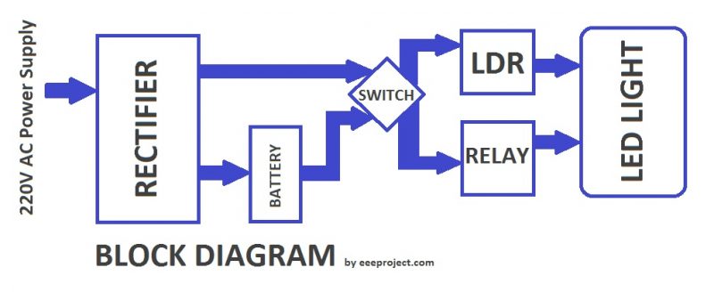
There are three modes of switches in our circuit. The traditional on/off switch is a simple switch that we use in our everyday appliances. A relay is used in the circuit in order to sense the ac main supply and will keep the lamp in off mode. An LDR (Light Dependent Resistor) is used to sense the light and turn on/off the lamp according.
Principle of automatic emergency light circuit

When there is an ac power supply, the battery charges through the rectifier made up of diodes meanwhile the LEDs will not glow as Relay senses the ac power supply. At the same time, the LEDs will also glow as the LDR senses no light. When the Ac power supply is stopped the LEDs will start glowing if there is no presence of light sensed by the LDR.
The LDR (Light Dependent Resistor) is present in light, its resistance value becomes very low and as the result, the transistor value (which has the base current from the LDR) becomes high and so do the LEDs. When the circuit is placed in the dark i.e the LDR senses no light then it has a very high resistance in mega ohms order. In this case, the base current of the transistor is very low which causes the LEDs to turn ON.
Automatic Emergency Light circuit

Circuit Components
- 12v Step Down Transformer
- Diodes (or a diode bridge)
- 7809 Voltage regulator
- LDR (Light dependent Resistor) 2 Mega ohms
- SPDT relay
- 9V battery 9Ah
- Transistor (BC548)
- 8 High brightness LED (3v, 15mA)
- A color LED (for current indicator)
- Resistors (10k, 1k, 10 ohms)
Automatic Emergency Light Circuit description
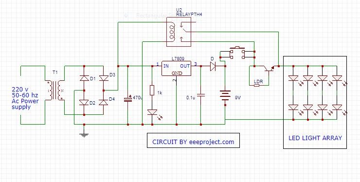
In the circuit step-down transformer is used to convert the AC 220V input power supply into 12v. The diode bridge is then used to convert that 12v ac output from the transformer into 12v dc output. After converting this 12v into dc there are some variable (Repel) characteristics in the voltage which are then minimized by using the capacitor of 470 microfarads. The LED connected after the capacitor is used for the indication of the current flowing through the circuit whereas the corresponding resistance is used to prevent the tiny LED from the 12v high voltage.

The 7809 voltage regulator is used to regulate the 12v up to the 9v which is suitable in order to charge our 9v battery. The IC has a built-in current limiting circuit and a heat sink which helps it to withstand high current as well.
The 6 high glowing LEDs are connected in such a way that may save our power. The two pairs of LEDs are connected in series and the three arrays having LEDs in series are connected in parallel. For each LED we had used a required minimum of 3.6 V and 20 mA in order to glow in full brightness.
The Relay is used to detect the AC power supply, the choke terminals of the relay are connected to the outputs of the rectifier. And the output switch is connected in between the positive end of the battery and the LED arrays.
Similarly, the LDR and Transistor setup is connected in parallel to the relay switch in between the positive end of the battery and the LED array in order to act as a photoswitch. Along with the two switching setups a simple switch is connected in parallel so that the LED light could be turned on manually as well.
Procedure to implement the Automatic Emergency Light circuit
- Connects the components as per the circuit diagram shown.
- While making connections make sure that there is no connection between the AC and DC end of the circuit or else it’s going to blow everything off.
- Keep the switch at the On position and Give the AC main supply to the circuit, you will be able to see the battery is charging and the LEDs are not glowing. Now turn off the AC main supply and you will be able to see the LEDs are glowing.
- Now power off the AC supply, keep the switch on and keep your circuit in the light, you will see that the LEDs are not glowing, take the circuit in the dark and your LEDs will be glowing.
You may like to see Motion detector circuit
Advantages of Automatic Emergency Light system
- Automatic Emergency Light is a very simple setup and could be implemented very easily.
- Components used in Automatic Emergency Light circuits are very easily available and at a very cheaper cost.
- It is a very good choice when it comes to saving energy.
Application of Automatic Emergency Light Circuit
- An automatic Emergency Light Circuit could be used in places where the light gets on automatically as the power goes off.
- It could be used as an emergency lamp in homes and other places.
- It could be used in study rooms and workplaces in order to avoid sudden power failures.
- An automatic Emergency Light Circuit with a battery charger is very helpful as a backup power supply.
You may like to see Sun Tracking Solar Panel
Do share your thoughts below about how you like the article or if you do have a suggestion about the article.


9 thoughts on “Automatic Emergency Light – Working, Principle and application”
nice work ! 🙂
nice info 🙂
very helpful
nice !
hi,
I want to make an automatic emergency light circuit which must have below features.
* Power supply without a transformer.
* Uses LDR to stop bulb from blowing in the day time or when there is a light.
* Has an indicator as well as protection from over charging.
* Should indicate for charging, full charge and low battery.
🙂
I am trying to analyse your circuit and to me it looks like the LED LIGHT ARRAY will never turn on if the switch between the 9V battery and the LED LIGHT ARRAY is not pressed ON. How does the 9V reach the LED array if this switch is open? Can you explain?
I Your explaination,, you said that if the switch between the 9v battery and the LED light array is not pressed ON. This means that the voltage/ current can not pass through the switch because it’s off. Now try to Press the switch ON and see what will happen to the LED light array..
will you just give a proposed idea to create automatic room lighting system for the future ?
Am interested in building this circuit, please what is the voltage of the filter capacitor?