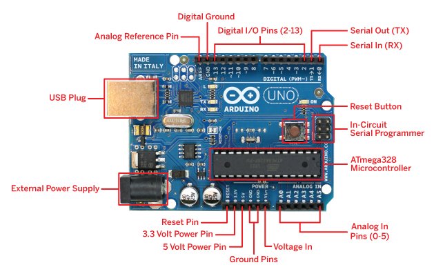
Arduino Uno board Description
The Arduino Uno board is the most popular board and mostly referred for the beginners as they are super easy to begin with, it does not requires any specific arduino uno software instead of that all you need is to select the arduino uno in the device option before uploading your program. There are plenty of arduino uno boards look different from the one as shown. But they all have plenty of the same components given below.
Voltage regulator
The Arduino Uno can be powered by USB cable or directly supplying 9-12v from the barrel jack. The circuitry operates at 5v dc which in case input more than that is regulated with the help of 7805 voltage regulator. The 7805 voltage regulator ic is used regulate the voltage supplied to the arduino board and manage it through processor and other elements.
Crystal Oscillator
There are certain case when the processor has to deal with time-signal issues, in order to balance it the crystal oscillator is used. The crystal oscillator is the only way the arduino is able to calculate the time. There is a number printed on the top of the crystal. The number indicates the frequency of the crystal, in most of them the frequency is 16 MHZ or 16,000,000 hertz.
Reset Button
There is a reset button given which is used to restart the program running in the Arduino uno. There are two ways to restart the whole program.
- You can use the default reset button.
- You can connect your own reset button at the pin labeled as Reset.
Arduino uno board General Voltage pins
There are following output voltage pins.
- 3v output pin
- 5v output pin
- GND (ground)
Most of the arduino components operate at 5v or 3.3v and so can be powered with these pins. There are several ground ports which can be used to give ground to your circuit and components. There is a Vin pin which can be used to power the arduino uno from an external source.
Note: The voltage must be 5v DC in case the arduino board is powered using external source.
Analog i/o pins
The Arduino uno board has 6 analog input and output pins from A0 to A5. The pins are best used in case of the analog sensors. The analog pins can read the analog signals from them like temperature, proximity, humidity etc and converts them into digital values that can be read and processed by the microcontroller.
Microcontroller in Arduino uno board
Different Arduino boards have different microcontrollers. It can be said that is the main component in the overall Arduino board. The main IC is a bit different in different arduino uno boards. The microcontrollers used basically are of ATMEL Company and it is necessary for you to know what IC you are using in order to load your program in it. You can easily read the information on the top of the IC and select the corresponding from the option given in the arduino software. For more information about the ic you can refer to the corresponding datasheet.
SPI Ports
The SPI (Serial Peripheral Interface) is considered for an expansion of the output. In most of the cases the ICSP Pin as an small programming header in Arduino Uno consist of RESET, SCK, MOSI, MISO, VCC and GND.
Power Indicator LED
When you power up the Arduino uno board, there must be an LED light up which will indicate the board is powered up correctly. In case you don’t see the glowing light, there must be something wrong with the connection you’ve made.
TX and RX Pins
In the Arduino Uno board there are two LED’s labeled as TX (transmitter) and RX (Receiver), Same are labeled on the pin 0 and 1 respectively. These pins are used for serial communication and the corresponding LED glowing indicated fi the data is being sent by TX and if the data is being received by RX. The TX LED flashes at the different frequency which depends on the baud rate being used by the arduino board to transmit.
Digital i/o pins
Arduino uno board does have 14 digital i/o pins (input/output pins) out of which contains 6 PWM output (Pulse width modulation). The digital pins can be configured to read logic values such as 0 and 1 or can give logic (0 and 1) output for different modules such as LEDs, Relays, etc. there is a symbol “~” corresponding to the PWM pins.
Additionally there is AREF which is used to set an external reference voltage as the upper limit to the analog input pins. The external reference voltage is usually in between 0 to 5 volts.
Summary
Arduino uno projects are very simple for beginners to start with and there are plenty of other websites where arduino uno tutorial are easily avaliable. You may want to go through arduino uno datasheet for more description about Arduino Uno board or you may want to see arduino uno pin diagram. There are plenty of other popular arduino boards available such as Arduino nano, Arduino Mega 2560 and many more.
Feel free to comment below about how you feel about !

14 thoughts on “Arduino Uno board – Full Description”
What is the min & max voltage it work??
you can give a supply upto 12v DC from that external power supply, however all the internal components works on 5v DC.
hope you’d liked it 🙂
not good lanja
A simple arduino uno pin diagram for simulation would be very helpful, nice work anyways
Is there a different arduino uno software ??? because it is not working with the arduino software i am currently using.
Very nice
Please provide an arduino uno tutorial 🙂
what is arduino uno ?
can i make my own arduino board which supports programming from arduino software ?
I need to use the two ultrasonic sensors, have to get the signals from 8 ir sensors and have to control a hubby servo motor and 4 motors.
Which kind of arduino should i go with and why ?
Pheww !
Can i make a traffic light control with the help of arduino board ?
I’m new to arduino and embedded stuff. I kinda like Arduino boards though. i can make any thing i think of, all i need to know is the set of code and components which fits my need. That’s very cool !
Am working on a project ( microcontroller base tillage depth sensor) how do I go about with the programme, I’m agricultural engineering students can you help me out
you are using the color red to point to components on the uno boards. Red doesn’t show up well when printing the info for future reference.