JK flip flop
This type of flip flops was invented by a Texas instrument engineer, Jack Kilby. He is the scientist who has invented the first integrated circuit. So, the ‘JK’ in JK flip flop circuit came from the name of the scientist who invented it that is ‘Jack Kilby’.

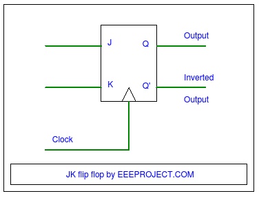
It also has two input units like other sequential circuits. The set input of JK flip flop circuit is known as ‘J’ and the reset input of it is known as ‘K’ input. There are many flip-flops design which are currently being used, but the most common one which is widely used is JK flip flop circuit. It is also a sequential circuit.
JK flip flop circuit can also be referred to as a gated SR flip flop which has an additional unit that is clock input. There is an additional clock input, because it prevents the invalid conditions which can occur during the set and reset inputs.
Basic Components of JK flip flop
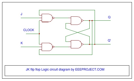
It has two NAND gates and the input of both the gates is connected to different outputs. It is connected in a way that both the inputs are interlocked with one another. So, it basically produces a toggle action and work on it.
Truth Table for JK Flip Flop Function
| same as for the SR Latch |
Input | Output | Description | ||
| J | K | Q | Q | ||
| 0 | 0 | 0 | 0 | Memory no change |
|
| 0 | 0 | 0 | 1 | ||
| 0 | 1 | 1 | 0 | Reset Q » 0 | |
| 0 | 1 | 0 | 1 | ||
| 1 | 0 | 0 | 1 | Set Q » 1 | |
| 1 | 0 | 1 | 0 | ||
| toggle action |
1 | 1 | 0 | 1 | Toggle |
| 1 | 1 | 1 | 0 | ||
What is a toggle action?
Toggle action consists of clamps which operate through a unique linkage system of pivots and levers. It can be of different types, according to the state it is therein. And, the best part about this action is that it is fast.
The clocked unit of the JK flip flop circuit is represented by symbol ‘D’.

Working of JK flip flop
- If the inputs of both the set (J) and reset (K) are different, then the output ‘Q’ has the value of output ‘J’ that is the set.
- All this happens on the next edge of the clock input.
- Suppose if both the set (J) and reset (K) inputs are low, then no change will occur in the output ‘Q’.
- If at the clock edge both the set (J) and reset (K) inputs are high, then the output ‘Q’ will move or toggle from one state to another.
- The best advantage of this circuit over all other flip flops is that it has no ambiguous states.
- That is the reason it is referred to as the most versatile circuit.
- The basic thing which is required for the JK flip flop to work or change the state is the toggle action.
- And, for generating toggle action high values of set (J) and reset (K) input is must.
- As, when we have high values then only toggle action occurs.
You may also like how to test a diode
Applications of JK flip flop circuit
- It is widely used as a sequence detector.
- The major use of this circuit occurs in the binary counter.
- It is also used as a frequency divider.
- The circuit is also applied for calculating the shift register.
- And, with the help of this sequential circuit we can also calculate serial data transfer values.
- It is also used for calculating the parallel data transfer values.
So, whenever both set and reset input can swap states then the action occurs and JK flip flop circuit works. You may also like Sun Tracking Solar Panel

19 thoughts on “JK Flip Flop [Explained] in Detail”
is there any way i can convert the JK flip Flop into SR Flip Flop? Just a Curiocity 🙂
Yes. There is. We study about conversion of S R flipflop to J K flip flop in the 3rd semester Engineering.
That’s the exact OPPOSITE of what you were asked.
what does j k in jk flip flop indicates ?
Jack Kilby
Jack kilby
i want a working model of JK Flip Flop with the help of logic gate ic. Can you guide me to do so ?
What is the function of clock in a flip flop ?
The clock pulse is used for the synchronisation and act as an additional control input in flip flops.
sir please explain about modes in jk flip flop
Read the TRUTH TABLE
Is the flip flop available in IC package ?
Is jk flip flop excitation table correct ? when j = 1 and k = 0 and q = 1 and q’ = 0 ??
Its a bit confusing to me..
Nice, Very helpful 🙂
i do not understand the concept of toggle. Is it means the switching between on and off or otherwise ?
A JK flip flop is a refinement of SR flip flop in that indeterminate state of the SR type is defined in the JK type.inputs J and K behave like inputs S and R to set and clear the flip flop (note that in a JK flip flop,the letter J is for set and the letter K is for clear).
Thanks so much for your support
hi, i am doing a class assignment which involves jk flip flop. If i implement the your circuit in proteus(simulation software) it gives grey color inputs to 2nd set of nand gates cause there is no output.
Grey in proteus means that the state is undefined.
So, can you tell me how to get output in that case.
linkage system of pivots and levers??? You should fire your translator.