Samuel Hunter Christie invented the Wheatstone bridge in the year 1833, which became popular with the works of Sir Charles Wheatstone in 1843.
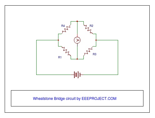
An electrical circuit that is set up to measure the unknown value of a resistor and creates a balance between the two legs of the bridge circuit is called a Wheatstone Bridge. As shown in the figure below, three resistances are known (one is variable/adjustable) and the fourth one has to be found out. We will be doing this with the help of ohm’s law.
Compared to the other measuring instruments such as voltage divider, the concept of Wheatstone bridge is widely used because of the accuracy in its measurement of resistance.
Components of Wheatstone bridge experiment
- A resistor with an unknown resistance value.
- Two resistors (with known resistance value)
- Variable Resistor (a device like Rheostat or Preset could work)
- Voltage/DC source
- Galvanometer (or any device which indicates the voltage difference or the flow of current)
- Connecting Wires
Circuit Construction
A Wheatstone bridge is a bridge-type structure having four resistors, three of known and one of unknown value.
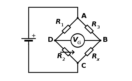
Here R1, R2, and R3 have known values among which R2 is adjustable and finally Rx is the value to be measured. Along with these resistances, a galvanometer (Vg) is there between B & D, and a DC supply between A & C.
Working Principle of Wheatstone bridge
Now according to the Wheatstone bridge principle if the ratio of the two resistances (R1/R2) on one edge is equal to the ratio of the two resistances (R3/Rx) on another edge then there will be no flow of current between the midpoints of the two edges of resistance. This condition of the bridge is known as the Balanced Bridge Condition.
In the Balanced Bridge condition, the current through the galvanometer is zero and also the voltage difference between the points B & D becomes zero, i.e., at both points voltage level would be the same.
Writing equations for the balanced bridge condition would look like:
R1/R2 = R3/Rx (or) R1 * Rx =R2 * R3
Thus, Rx = R3 * (R2/R1)
This detection of zero current in galvanometer is of high precision, thus depending on the level of precision of known values, the unknown resistance can be found with the highest rate of accuracy and precision.
In the Wheatstone bridge experiment, one resistor should always be variable in order to obtain a balanced condition. The Circuit performs at its best when the regulated voltage source is used, instead of the current with repelling characteristics.
Example Circuit:
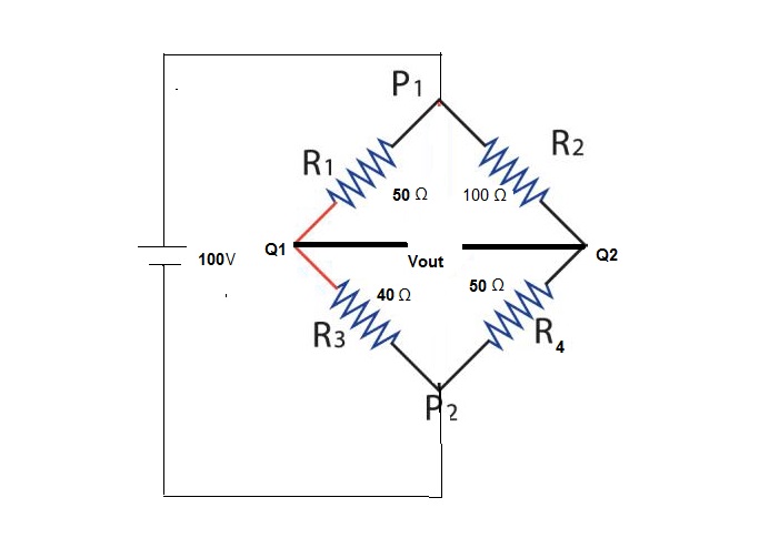
Let us consider the below circuit where the bridge is in an unbalanced condition and we need to calculate the voltage difference between Q1 and Q2, i.e., Vout and hence the value of R4 needed to make the bridge balanced.
As per the voltage division law,
Vq1 = (R3/(R3+R1)) * Vs ,where Vs =100volts (voltage source)
putting values of R3 = 40 ohms, R1=50 ohms ,and Vs= 100 volts, we get
Vq1 = 44.4 volts
Similarly, Vq2 = (R4/(R4+R2)) * Vs
putting the values, R4 =50 ohms, R2 =100 ohms, and Vs =100 volts, we get
Vq2 =33.3 volts
Thus, Vout can be found as,
Vout = Vq1 – Vq2
So, Vout = 44.4 – 33.3 = 11.1 volts
Now to make the bridge balanced, we can find a suitable value for R4 as done below:
R4 = R2 * (R3/R1)
putting the values of R1, R2, and R3, we have
R4 = 100 * (40/50)
= 80 volts
Therefore, R4 = 80 volts is the value of resistor which should be used to make the bridge in a balanced condition.
Applications of Wheatstone bridge
The circuit has many applications, which could easily be found in our daily lives. A few of them are discussed below.
Application in Measuring Strain
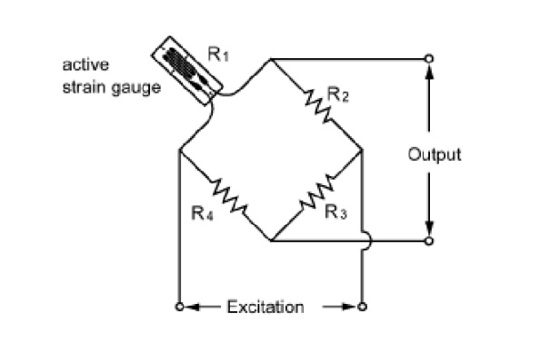
When the resistance varies in proportion to the strain present in the device, strain gauges are usually used. In practice, the resistance range is from 30 ohms to 300 ohms. Since the change in the value of resistance may be a fraction of the full-scale value thus the Wheatstone bridge is the best suitable for higher precision.
For this application, the strain gauge replaces the unknown resistor. Here R2 and R4 would have the same value and R3 is adjustable. Therefore, without disturbing anything else, a rheostat is varied until the galvanometer shows a null deflection. This null deflection implies that the bridge is in a balanced condition and no strain is there on the gauge.
Light Detector Application
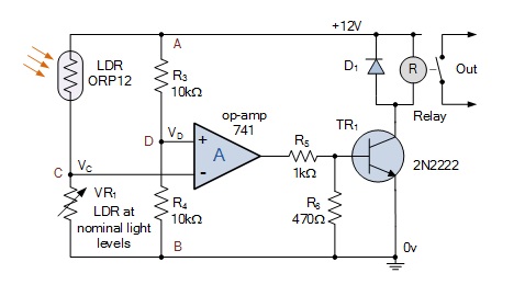
Light Detecting sensors use the Wheatstone Bridge.
Likewise, in this application also one edge consists of the two fixed resistances and the other edge has photoresistive sensors (LDR) and a potentiometer (Variable resistor).
The resistance of LDR does vary as the intensity of light varies, and with the help of potentiometer, one can, therefore, observe that at what intensity of light the balance point is achieved.
There is another advantage where one can note, before and after what amount of light the current flows in a positive as well as in a negative direction from one edge to another.
Other Applications
- Used in Light detecting devices.
- For measuring the changes in the pressure.
- For measuring the changes in the strain of the circuit.
- Used for the Sensing of mechanical and electrical quantities.
- Also, photoresistive devices use this circuit.
- Thermometers also use Wheatstone bridges for the temperature measurements which need to be accurate.
- Values like capacitance, inductance, impedance, etc. can be measured with some variations in the Wheatstone bridge circuit.
Limitations of Wheatstone Bridge
Along with all these advantages, there are a few limitations of the Wheatstone bridge as well, such as:
- Readings may be inaccurate under unbalanced conditions.
- The range of measured resistance varies from a few ohms to megaohms.
- Susceptibility for high dc current is not there.

23 thoughts on “Wheatstone Bridge Circuit Working Principle and Application”
Very helpful
Thanks Nancee !
is it possible to use the wheatstone bridge as a switch ?
Yes it may. I believe its up to your creativity. 🙂
Can we use the Wheatstone bridge circuit for calculating power ?
I do not understand the concept of calculating the power with the help of wheatstone bridge.
Can i use both voltmeter and ammeter in the balance of Wheatstone bridge ?
yes, You can use any indicating device in order to detect the balance condition in the Wheatstone bridge.
To be more practical just vary the resistor values in order to decrease the quantity then aquire the zero value, that would be your perfect balance condition.
experiment on application of wheatstone bridge when working with only two resistor one known and one unknown
Yes its an old and simpne wheatstone bridge experiment in which another resistor sigment is made by a conductor wire.
The ballance point in the wire is found by varrying the position of the pot and then the redistance of two end of wire is calculated by its length-thickness with its resistivity. Then those resistor values are used in the wheatstone bridge experiment in order to find the unknown resistor value..
is there any way to determine the resistance value if you have only single known resistance and some piece of wire ?
Yes it is, You need to use a conductor wire on the other side and have to vary the position of the wire attached on the middle in order to obtain the balance point as we do in wheatstone bridge.
Then put the length of those wire pieces in place to other known resistance values and calculate the unknown resistance !
does the wheatstone bridge is used in aircraft ? If yes then where and how did they use the bridge circuit ?
Wheatstone bridge are used in monitoring the temperature and pressures in the aircraft. It is also used to monitor hydraulics and tire pressure.
I use the multimeter in my wheatstone bridge along with the wire with a pivot which makes the two adjacent resistance edge and a known resistance. Whenever i touch the conductor of the unknown resistance the voltage from the balance point fluctuates.
can you explain the possible cause ?
Well its known that our skin conducts the electricity. When you touch the conductor it disturbs the current balance in the circuit. That would be the possible cause for you to see the fluctuation.
Hope that helped you.
What is the industrial application of wheatstone bridge circuit apart from manufacturing very low resistances ?
Nicely explained !
but i do not get the point of using wheatstone bridge circuit ? Can’t we simply use the multimeter to measure the value of the resistance ?
If we want to display the resistance in degree C, than we need wheatstone principle in work. Otherwise manually we can do it by multimeter.
Can you publish a post on measuring the resistance of any conductor with the help of Wheatstone bridge ?
Keep up the great work guys.
Great
If we want to display the resistance in degree C, then we need wheatstone principle in work. Otherwise manually we can do it by multimeter.