Impedance is the hindrance offered by the electrical circuit in the flow of current in an AC circuit. Basically, it is a combination of resistive and reactive components(due to inductors and capacitors). It follows the principle of ohm’s law. Also, we can say that impedance is just like a resistance in the dc circuit, therefore having the same unit as resistance,i.e., ‘ohm’.
Now, many questions should pop up in our minds.
How does this impedance differ from resistance, although having the same unit?
What does this impedance consist of? And many more questions like that.
Isn’t it?
Well go through the full article and you will get all the answers.
AC Circuits
Alternating circuits are those where we have sinusoidal voltage supply and hence the sinusoidal current. These are quite different from those of dc circuits. Here, one term will come, again and again, phasors.
Phasor is a way of representing a complex number which further represents the sinusoidal function whose initial phase(θ), amplitude (A), and angular frequency (ω) are time-variant. We will learn its application as the article proceeds.
AC Resistance with a Sinusoidal Supply
By ohm’s law, we know that in a dc circuit, the voltage across a resistor and the current through it has a linear relationship. Now, let us examine the case of an AC circuit.
The voltage here will be an ac voltage with a sinusoidal waveform. The expression of voltage can be written as
V = Vmaxsin(wt + 𝛉),
where, Vmax is the maximum amplitude and ‘w’ is the angular frequency.
Similarly, the current produced in the circuit will be sinusoidal and can be expressed as
I = Imaxsin(wt + 𝛉).
Now, you must observe one thing here. Ask what?
Yes, you should note one thing that is here, we do not have any phase shift, i.e., both voltage and current have the same angular frequency with a 𝛉-degree shift. Therefore, we say that in the case of a pure resistive ac circuit, both voltage and current are in-phase.
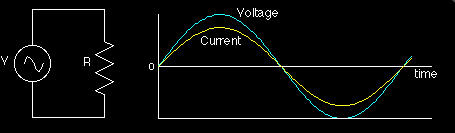
In the circuit above, we can see that a sinusoidal voltage is applied at the source. This voltage is time-dependent and will produce a current in the resistor which will follow the voltage polarity with the same or different amplitude (depends on the resistance value).
Applying the KVL in the circuit, we have
V(t) = I(t) * R
= Imaxsin(wt + 𝛉)
So, in purely resistive ac circuit the current waveform follows the same sinusoidal pattern as the voltage, i.e., the current varies in proportion to voltage.
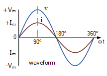
Sinusoidal waveforms for AC Resistance
Seeing the waveform, we can say that the voltage and the current rise happens at the same frequency and similarly for the fall in both quantities. Therefore, from waveform also it is proved that both voltage and current have no phase shift and hence in-phase.
The same result comes from the phasor of the above ac network as well.
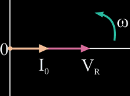
Phasor Diagram for AC Resistance
We must know that phasor represents the RMS value of quantities. Thus, to represent voltage and current we need to divide the maximum value of both the quantities by √2.
Vrms = Vmax / √2
Irms = Imax / √2
Now, you may ask a question that it looks the same as a dc circuit having a linear relationship then what is the difference?
Well, actually there is no difference (until inductance or/and capacitance is /are present) but just that in the dc circuit we call it as resistance, and here in ac circuit we call it as impedance.
AC Impedance
Again, as discussed earlier AC impedance when only resistance is connected as an energy-absorbing (passive) element then:
V = Z * I
where Z = impedance of the circuit
Z is generally defined in a complex form as it depends on the frequency. For example,
let Z = R + jX
where R = resistance of the circuit and
X is the reactance of the circuit, j is called iota and it is used to show the imaginary part of the number.
Therefore, Z = (V / I) Ω
In the case of a purely resistive circuit,
Z = R +j0 = R (Ω)
In cases where other passive elements like capacitors and inductors are connected.
Power Factor
The power factor is the cosine of the angle between the voltage and the current. Since in ohmic circuit the angle between the voltage and the current is zero, therefore power factor, cosႴ = cos0 = 1, i.e., unity power factor (UPF).
One more factor that we can calculate here is Power.
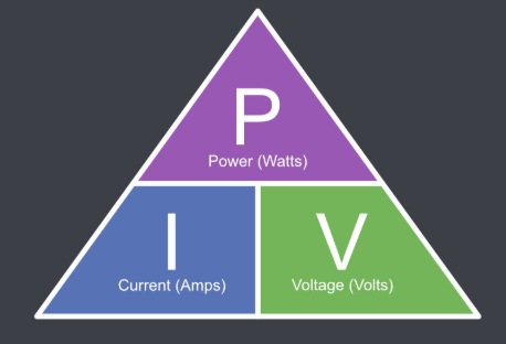
Then the instantaneous power consumed by the resistor is given as:
P = V*I = Vmaxsin(wt) * Imaxsin(wt)
= Vmax * Imax sin2(wt)
Therefore, P = Pmax sin2(wt)
where, Pmax = Vmax * Imax
Average Power
Average power is the dc power and is absorbed by resistor only. The average power in a reactive or resistive circuit depends on the angle between the voltage and the current. Since 𝛉 = 0 the power factor equals one, so the average power consumed by an AC resistance is given by ohm’s law:
P = V*I = I2R = V2/R
In daily life, ac circuits such as heating elements and lamps have only ohmic resistance and negligible value of inductance and capacitance.

In such circuits, we can use both Kirchoff’s law, ohm’s law or any other circuit rule to get all the parameters of the circuit. It is more likely dc circuit only until inductance and capacitance come into the play. Usually, we use RMS values with such rules.
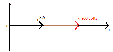
Example 1: AC Resistance
Consider an electric lamp, which has an ac resistance of 100 ohms is connected across a 300 volts AC single-phase supply. Calculate the current drawn from the supply and the power consumed by the lamp. Also, show the phasor relationship between the voltage and current in the lamp.
The current from supply:
I = V/R = 300 / 100 = 3 Amperes
The active power consumed by the lamp
P = I2R = 32*100 = 900 watts
Also by other formulas of power:
P = V2/R = 3002/100 = 900 watts
and P = V*I = 3 * 300 = 900 watts
Therefore, we can see that using either of the formula gives the same result.
Since 𝛉 = 0, the phasor, in this case, will be in the same direction for both voltage and current as:
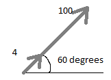
Example 2: AC Resistance
Consider a sinusoidal voltage supply as V(t) = 100cos (wt + 60o) is supplied to a pure resistance of 25 ohms. Find its peak value of current and impedance of the circuit. Also show the phasor for the same.
Now, this sinusoidal voltage can be written in phasor form as V = 10060O volts
By ohm’s law, we have
IR = VR /R = 10060O /25 = 4
60O Amps
The phasor diagram representing the above conditions will be as:
Summary of AC Impedance
There are certain points that you must remember when it comes to ac impedance with a pure ohmic element.
- Voltage and current are in-phase always in case of a purely resistive element. This changes practically with even a small introduction of inductance and capacitance.
- As 𝛉 = 0, therefore the power factor in the ohmic element is again always Unity, commonly called as unity power factor(UPF).
- The current follows the voltage in every manner except in amplitude. The maximum and minimum peak of current and voltage will be at the same time. Also the graph between them, in this case, will be linear and the slope will give the impedance.
- Impedance, Z is actually a complex number consisting of both real and imaginary terms but in this case again as the reactance is zero, Z will have only real part that is the resistance. Z = R + j0 = R.
- Therefore, applying ohm’s law in these circuits will give the required parameters.
I hope you have got a good intro with the impedance in ac circuits. Further in our next tutorial, we will be seeing the effect of inductive and capacitive loads in the ac circuits and its phasor relationship.

For any other query regarding the article, you can comment below and I’ll be happy to answer them all.
