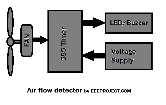
What is Air Flow Detector Circuit
Air flow detector circuit is widely used in many appliances, as it provides a visual indication of the rate at which air is flowing. Wherever it is necessary to detect the rate of air flow or presence of air this circuit is used, as this provides a clear picture of air in a given space.
The most common example of air flow detector circuit is engines. This circuit is used in engines to get the estimate of air flow within it, so that we may get to know how much more fuel we need to add to it for its proper functioning.
Principle of Air Flow Detector Circuit
This circuit basically works on a simple principle in which the basic component which is used for detection is resistance temperature detector.
The two main components on which circuit works are as follows:
- Air present in the given space work as an insulator
- Variation that occurs in resistance with temperature
If you are using an incandescent bulb, then its filament works as the sensing part of the air flow detector circuit. The proper functioning of this filament is necessary for correct detection.
- So, if suppose there is no air flow then we will see high resistance in the filament.
- And, if there is any air flow in a particular space, then the resistance of the filament will begin to drop. The reason behind this is that when the air is present, it removes some of the heat that is generated in the filament and as a result the resistance drops.
The circuit is incomplete without the zener diode, as this diode works as a voltage regulator in the circuit. And, it is recommended to use the proper zener diode as without a proper one the efficiency of the circuit can be affected in heavy loads.
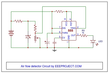
The important components of the circuit are as follows:
- LED bulb
- Resistances
- Battery
- Air flow detector
- 555 IC (Integrated Circuit)
- Filaments
You may also like Subwoofer Amplifier Circuit Explained with Application
Working of Air Flow Detector Circuit
In spite of having a difficult function, the working of the circuit is quite easy.
- The current will flow through the resistor
- The resistor will get heated up, as the current flows through it
- Air will pass through the resistance temperature detector
- Air works as the insulator, so the resistor will cool down a bit
- As a result, resistance will start to fall
- And, the resistance temperature detector will witness the decrease in the voltage flowing across through it
- The resulted variation in the voltage will be estimated through a timer circuit which is attached in the detector circuit
- And, this provides a clear indication of air flow in the engine with the help of this circuit
- The brightness which is the output result varies proportionally to the air flow across it
So, this is how the complete circuit works and detects the air flow for various appliances and systems.
You may also like Arduino and Bluetooth module Circuit
Application of Air Flow Detector Circuit
- Wherever it is required to estimate the amount of fuel present in the engine, this detector works best there. For example, air flow detection in car engines to know the amount of fuel that is needed by the engine.
- The air flow detector can also be used to detect the temperature of the circuit or it can be used as a temperature detector circuit in various appliances.
- Devices which are based on temperature sensing also have this detector in them. For example, a fan can have this air flow detector circuit in it.
- It is also used in Spirometers.
- To detect the air take in the combustion engines.
- For the detection of leak in pressurized air systems.
- For the measurement of industrial gas flow.

2 thoughts on “Air Flow Detector Circuit Working and Application”
here is the circuit ! but where is the rotating stuff which measures the flow of air ?
sa10-28-2023
(1.) Hi, there.
(2.) What are the values for the components?
(3.) Thanks.
(4.) Toodles!