A half-wave rectifier is a simple circuit that is basically used for converting an AC voltage to the DC voltage. It is a simple diode or a group of diodes which converts AC (Alternating Current) voltage into DC (Direct Current). It is used in the end number of electronic devices.
Principle of Half Wave Rectifier
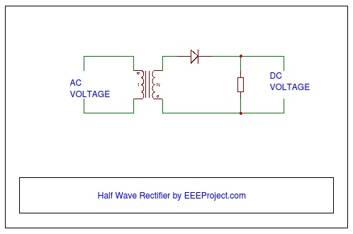
The half-wave rectifier circuit is a diode. And, a diode works and allows current in only one direction and blocks it in another one. So, the basic principle on which rectifier works and is constructed is the working of a diode only.
If a circuit, contains a group of diodes then the proper arrangement of all the diodes is a must. The simplest known form is half-wave.
Components required
- The stepdown transformer is used for reducing or increasing the AC voltage.
- Step-up transformer is used for increasing the voltage from low to high, whereas a step-down transformer is used for reducing the AC voltage from high to low that is vice-e-versa of the step-up transformer
- The step-down transformers are the main components in the potential transformer which has a very different function than that of the rectifier.
In the rectifiers, mostly step-down transformers are used as the AC voltage source required by the diode is very less.
Working
And, a step-down transformer has the number of turns in the primary winding than the secondary winding; that is why the AC voltage is reduced when it moves from the primary to the secondary winding.
- An AC source provides the AC (Alternating Current) voltage to our rectifier circuit.
- Resistor or a load is an electrical component that is used for restricting the flow of current to a certain level.
- The diode is a basic and important component in the rectifier. The electronic device that blocks the movement of current in another direction, when it is moving in one direction.
- Electrolytic capacitors usually act as a filter in the rectifier circuits. They are used in the circuit for reducing the ripple voltage. While attaching the capacitor to the rectifier circuit, you should properly connect it as such that the polarity matches, because then only current can pass through it. This should be kept in mind because if the electrolytic capacitor is attached in the reverse polarity, then it may get damaged.
The diode should always be placed between the transformer and the resistor.
These rectifiers can be of two types:
- Positive Cycle
- Negative Cycle
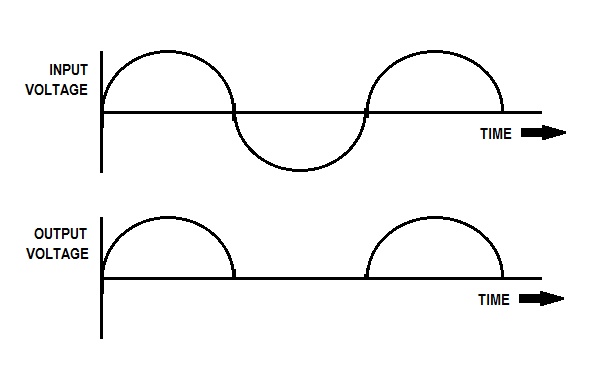
Working of the Half Wave Rectifier
The working of the half-wave rectifier is completed in two cycles that are positive and negative cycles.
- The diode is under the forward bias condition during the positive half cycle. And, the current is conducted to the load resistance.
- So, the voltage is established across the diode.
- And, the diode is under the reverse bias condition during the negative half cycle. And, so there is no movement in the circuit and current flow equals zero.
- So, only the voltage which was established in the diode is there; which is the net result of the positive half cycle of the circuit.
- And, the generated output voltage is responsible for pulsing the Dc voltage from the rectifier circuit.
Also, see 3 phase transformer

9 thoughts on “Half Wave Rectifier: Principle & Working”
Can we make half wave rectifier without the transformer ?
no buddy bcoz at on daily basis the current we use is ac and in order to use half wave rectifier we need dc so a transformer generally converts ac into dc
Bro simple answer if the input AC voltage is small and a diode can handle it the there is no need of it
If you are dealing with high voltage lets say a 3-pin plug which outputs 220V (in India) and most of the devices require only up to 5V or 10V or 15V soo in this case you have to use a step down transformer
Could we use the half wave rectifier as a chopper ?
Very helpful half wave rectifier
is this the one called diode bridge rectifier ? 🙂
How to charge my battery with the rectifier you made ?
Nicely explained.
However, i have a doubt why does we use the capacitor at the output of the rectifier ?
I mean, we always get the ripple at the last ! Isn’t it ?
Can the Half wave rectifier be used to get the output similar to the chopper with minimum or no ripple in the output voltage ?