LED Driver Circuit
LED i.e., Light Emitting Diode is a special kind of diode that emits energy in the visible band of the electromagnetic spectrum. However, it conducts in forward bias the same as the p-n junction diode. It is used as an optoelectronic device.
Now let me ask you a simple question. At our home we get 230 volts AC supply, can we give this directly to an LED? The answer should be Of course not. This is because an LED needs a constant current input. Thus to serve this purpose, we need a driver circuit.
In this particular article, we will be learning about the design of a 230 volts LED driver Circuit. Generally, an approach of using a transformer for AC to DC power supply is widely used. But just think will it be a good option for driving a load like an LED? Not at all. So let us try it out the other way.
Principle of LED Driver Circuit
I hope after the above discussion you are very clear with the aim of the article. Yes, we have to design a transformerless LED driver circuit (which can be used at home especially.)
The driver circuit design contains AC capacitors that are designed for high voltage and are connected line to line. The basic function of the capacitor is to limit the current of the supply. As the capacitor only reduces the current, high voltage is delt (rectification and regulation) in the later part of the circuit.
Components of a LED driver circuit
- Electrolytic capacitor (non-polarized 2.2μF)
- Four resistors (1KΩ,10KΩ, 22KΩ, 390KΩ)
- Bridge rectifier
- Zener diode (4.7V)
- An LED (Bright white LED)
- And, a polarized capacitor (47μF)
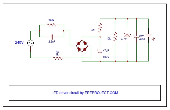
LED Driver Circuit Design
- To the main supply, an AC capacitor is connected in a line with the mains supply.
- Then, a resistor of 390 Kohm is connected in parallel with this capacitor. This is to discharge the capacitor in the absence of supply. One more resistor of 10Ω is connected between the mains supply and the rectifier which can be called fuse here.
- To make the incoming AC voltage as DC, we use the Full-wave Bridge rectifier. Its capability is 1.5A for current.
- Now, bridge rectifier output is filtered using a capacitor (C filter) of 4.7μF.
- Zener diode is used next for regulating the output of the full-wave bridge rectifier. Keeping in mind the current that goes to Zener, we have connected a resistor of 22 KΩ in series. The value of the Zener voltage is 4.7 volts.
- Once more the Zener output is filtered with a capacitor of 47 μF, and finally given to the LED (load).
Working of LED Driver Circuit
The X-rated capacitor is the most vital component here as we are designing a transformerless driver. Let us calculate the capacitive reactance as below:
Capacitive Reactance Xc = 1/2πFC
therefore, Xc = 1/(2π*50*2.2*10^(-6))
we have C = 2.2 µF
=1447.59
Therefore, from Ohm’s Law the capacitor current, I = V/R
putting values of V & Xc , I = 158 mA
Now, this current enters the rectifier. Also, the input to the bridge circuit is 230 V RMS. So Vmax = 230*√2 = 325.26 V. Thus, the capacitor filter must be rated for 400 V. After rectifier, the voltage will be around 305 V which further needs to be brought down to use it as an LED input.
Zener diode serves the purpose. Also, its power rating should be kept in mind along with a series resistor and its power rating. Let us first calculate the suitable value of series resistance.
Rs = (Vin – Vz )/( IL + Iz)
where Iz = 10 mA, IL = 5 mA
Vin = 305 V , Vz = 4.7 V
Therefore, Rs = 20020 KΩ
Now the power rating of this resistor needs to be calculated, as it determines the amount of power it can dissipate.
Ps = (Vin – Vz)2 /Rs
putting all the values, we get
Ps = 4.5 W
Lastly, the power rating of Zener Diode = Vz*(Vin – Vz)^2/Rs = 0.07 W
So the rectified regulated voltage along with the limited current is given to the LED load.
Also, watch Half wave Rectifier
Advantages of Driver Circuit
- It is simple and cost-effective as transformerless.
- Small size and have very weight.
Limitations of LED Driver Circuit
- The application here suits best for domestic use and single-phase supply.
- The capacitor used here may produce spikes with the fluctuations of mains.
Applications of LED driver circuit
- It is used for lightening and decorative purposes at home.
- It is also used in car, bikes and various other automobiles as an indicator.
- This circuit is also used in the combination with the doorbell to provide the indication.
- It is used in various domestic applications like commercial and residential lighting.
I hope you have gained some ideas about designing the driver circuit. I would love to see any new creative ideas on the same in the comment section below. Also, give your feedback on the article (design) above, so as we can keep on improving on the quality for you.
Also, watch Solar Battery Charger Circuit Explained in Detail

16 thoughts on “LED Driver Circuit Working and Applications”
its very cheap circuit, thanks
thanks vijay, glad you found it helpful
Hello sir, I want to make 36W driver Circuit for LED tube light. so can you share me the circuit diagram and its components list
Led Driver daigram
Can you make a circuit on a 5w led driver circuit which can charge a battery on parallel and glows the light when there is no power supply ?
John you can try it with a capacitor, as it stores energy and supplies the same when supply is OFF
Can this driver be use to drive 80 LED for example? if not how can I design a LED Driver to light 80 LED.
Thanks.
Well, I appreciate your interest here. As in general, most of the LEDs take current somewhere in 10mA to 30mA and voltage as 2 to 4 volts thus we can add the number of LEDs in parallel as per the ratings of the available LEDs.
Thank you.
Thank you so much for the circuit sir. After a long days I got a very reliable circuit.. i will try this. I have two questions on this, please reply
If LEDs will be in parallel the current across each led will be divided. Will the glow reduce?
If i don’t get 390k bleeder resistor can I use 470k 1 watt resistor..or 390k is a MOV?
Do you have a LED SMD Chip COB Lamp 5W driver diagram For car? The car have a from 12V to 14.8V. Led foward voltage is 6 – 7V, foward current is 700mA.
Thank you so much for the circuit sir. After a long days I got a very reliable circuit.. i will try this. I have two questions on this, please reply
If LEDs will be in parallel the current across each led will be divided. Will the glow reduce?
If i don’t get 390k bleeder resistor can I use 470k 1 watt resistor
How to make 40v 30w led driver circuit?
I need the circuit diagram for AC driver circuit for 5W led light.
Can you help me with it please..
2.2uf capacitor don’t drop any voltage? 2.2uf is voltage dropping capacitor or not? i want to know how much voltage will be at input side of bridge rectifier
How to make 50w led driver circuit?
Led Driver daigram