AC Waveform (alternating current wave) is the electrical voltage and current waveforms against time in an AC circuit. It shows how an alternating quantity changes with time.
Now as always, we must know why are we studying this! Isn’t it?
We have immense practical applications for this. From the generation of power (in power plants or the backup generators) to the power that comes to our house, everything is nothing but the application of AC circuit theory. To have a good knowledge of circuit theory, understanding ohm’s law is important.
I guess that’s a good motivation for you to learn more about the topic.
Interesting!! Isn’t it?
Alternating Signals
As the name says, an alternating quantity (signal) varies with time. This waveform can be of any shape (sinusoidal, triangular, trapezoidal, square, etc.).
In this particular article, we’ll be talking about sinusoidal waveforms only as they are the most commonly used. A sinusoidal wave changes its value with time but in a fixed pattern. The following figure shows the voltage across an ac impedance.
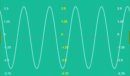
Well, you can easily see that from the waveform. The wave changes in a particular fashion and is hence the most useful among all other forms of alternating waveforms in the analysis of ac circuit theory. These signals may be AC electric potential difference or voltage and AC electric current. Also, these signals vary as positive, zero (crossing), and negative.
Let me tell you an interesting thing here!
If we use a half-wave rectifier the same waveform has only positive cycles and the negative cycles get eliminated. Also, using the full-wave rectifier will even invert the negative cycle and makes it positive.
Characteristics of AC Waveform
The basic characteristics of an AC waveform are as follows:
- Amplitude
- Frequency
- Period
Amplitude
The peak value or the maximum value that a waveform achieves is called its amplitude. This length is measured from the x-axis, i.e., the zero line. In other words, we can say that the maximum value of the signal in the half-cycle is known as its amplitude.
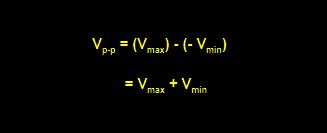
In a perfect sinusoidal wave, the absolute value of the Vmax & Vmin is always the same. Also as it goes from maximum to minimum value it crosses the zero line, the time axis. For non-sinusoidal or complex waveforms, these values may differ from each other. Sometimes, the peak to peak value is considered, Vp-p. This Vp-p is given by:
Frequency of AC Signals
The frequency of a signal is defined as the number of cycles it completes in one second. To be more specific, this frequency is the fundamental frequency. The formula to calculate the frequency is
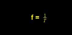
The SI unit of frequency is “Hertz”. Also from the formula, we can derive its unit as second-1. One more thing to note here is that the frequency is inversely proportional to the period of the waveform. It means the more the frequency, the less the period, and the less the frequency the more the period. This relation can be used where one quantity has to be varied with the other.
Now tell me, do you know what frequency we use in general for our electrical power system?
Any idea? Must have heard!! Think!!
Period
The period is nothing but the reverse of frequency. The time in which a waveform repeats itself is the fundamental period of that particular signal. Therefore, the formula for the period is given by

The SI unit of the period is “seconds”. Also by the formula, we can derive the unit as Hertz-1.
Both the formulas for period and frequency are important in ac circuit theory computations.
Calculations in an AC Waveform
Now, we have many practical signals in the form of an alternating waves. For example, the sound is an AC wave that traverses through the air medium. Therefore, to approximate the values of such waveforms, we need to find the average of the wave, RMS value, form factor (for sinusoidal waveforms), etc.
Average Value of a non-sinusoidal Waveform
So, what an average is?
Yes, the addition of all the quantities is divided by the total number of quantities.
But, what due to thinking! Can we use this here?
Of course not. That is because the above rule is for a discrete system and not a continuous one. So what should we do? Any idea?
Well, in such cases we need to find the area under the curve which gives us the average value in a continuous wave. Therefore, with the help of mathematics (Simpson rule, mid-ordinate rule, or the trapezoidal rule) we can easily find out the area and the average value.
Average Value of a Sinusoidal Value
The average value of the sinusoidal waveform is the average of all the instantaneous values of the voltage/current in a one-half cycle. This is calculated by finding the area under the curve for the half cycle.
Now, can you tell me why I said “half-cycle”?
That is because, for sinusoidal waveform, we have a graph for both the half cycles in opposite polarity that is one in a positive direction and the other one in a negative. Therefore, are under the curve for both the cycles will be the same but with opposite signs.
Thus, making the sum of areas equal to 0 always,
A = A1 + A2 = A1 + (-A1) = 0.
Formula to calculate the Average Value of any Periodic Waveform
Well, there is a pre-defined formula to calculate the average value. Consider a voltage waveform having period T, then the average can be calculated as:
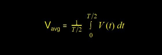
Why are we using T/2 here?
Yes, the reason is the same that we are calculating it for half the period.
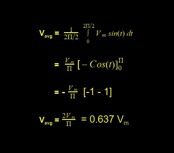
So let us calculate the average voltage value in the case of a sinusoidal waveform. Therefore, considering V(t) = Vm sin(t) where voltage is a function of time. Also from the waveform of the sine wave, it is clear that the period is 2. Putting all this into the formula, we have
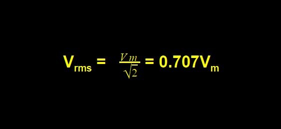
RMS Value of Sinusoids in AC Circuit Theory
The full form of RMS is the Root Mean Square value. This is the quantity that we use only for ac waveforms. As the name suggests it is the root of the mean of the squared values of voltages/currents (or any other ac quantity).
Now, you get a question here!
What do we mean by this RMS value? And also what’s the need?
Let us simply understand this. For example, we have a 15V battery. So it’s a dc right. But what if we wanna describe the same power in an ac circuit? We can’t simply say any value as it changes continuously with time. Therefore, for this reason, we compare the heat produced in both cases.
Thus, the amount of ac power that produces the same heating effect as that by a dc is called the RMS value of that ac signal.
Calculation of RMS Value of a Signal
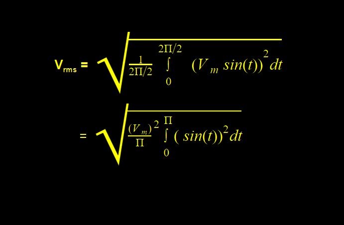
Let us consider an ac circuit with a varying voltage, V(t) = Vm sin(t) which varies with time.
Here, Vm is the maximum or the peak voltage of the waveform. Also, considering the sinusoidal waveform, we have the period of ‘T’ and frequency as ‘f’. The formula for RMS is given by:
To solve this, write the sine square function as:
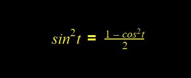
putting this in the main equation, we have
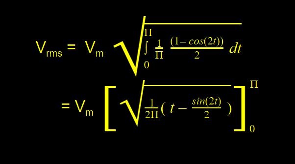
Solving the above expression, we have
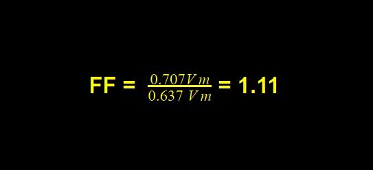
Form Factor & Crest Factor of AC Waveform
Though these are not much in use these days they may still help you to learn a few conventional methods. The form factor is given by the ratio of the RMS value to the average value of the waveform.

For a pure sinusoidal waveform,
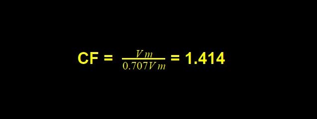
Also, the crest factor is given by the ratio of maximum value to the RMS value:

For a purely sinusoidal wave,
Let us now learn about some other ac waveforms.
Square AC Waveform
It shows the two states ‘ON’ and ‘OFF’, therefore they find most applications in digital electronics. Unlike the sine/cosine wave, it has a single positive value for a certain period and a single negative for the same time again. In other words, we can say that it has a flat top.
The period of the square wave is defined as the sum of its ON & OFF time or the sum of its positive & negative cycle time. Also, the ratio of its ON time to that of the total time is known as the Duty cycle.
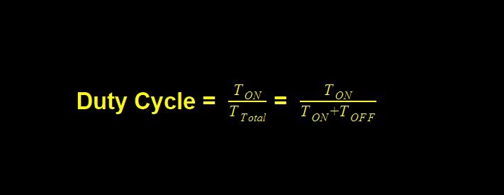
Also being the ratio of time, it is a dimensionless quantity.
Sawtooth AC Waveform
As the name suggests, the sawtooth wave looks like a sawtooth. It is basically of two types, namely a positive ramp, and a negative ramp.
Positive Ramp
It rises slowly with time (almost linear) and has a steep decrease in magnitude. The above circuit shows the positive ramp and you can play along to see the waveform with different amplitudes.
Negative Ramp
It is just opposite that of the positive ramp. It has a steep increase in the magnitude value and a slowly decreasing curve (almost linear). Just reverse the oscilloscope terminals to get the negative ramp and see practically that changing what results in what.
Isn’t it interesting?
Of course, it should be.
Triangular AC Waveform
Just like the sawtooth wave it also has a sharper peak edge but both rise and fall are slow, i.e., linear increase and decrease. These are also periodic and therefore, the rising and falling time is the same.
If we talk about the period then again both the positive and negative half periods are added together to give the period of the triangular wave. But these are used less in ac circuit analysis when compared with sinusoids.
To learn and simulate the circuits in a virtual lab that gives the same feeling as a real-world lab, click on the below poster. Explore the world of electrical & electronics with real-time simulation.
