Full Wave Bridge Rectifier Circuit
Broadly, the rectifiers are classified as the Full Wave Rectifiers and the Half Wave Rectifiers. Further Full Wave Rectifiers are designed in two ways: Full Wave Bridge Rectifiers and Center Tapped Full Wave Rectifiers.
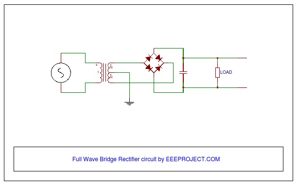
The Full Wave Bridge Rectifier Circuit is a combination of four diodes connected in the form of a diamond or a bridge as shown in the circuit.
However,
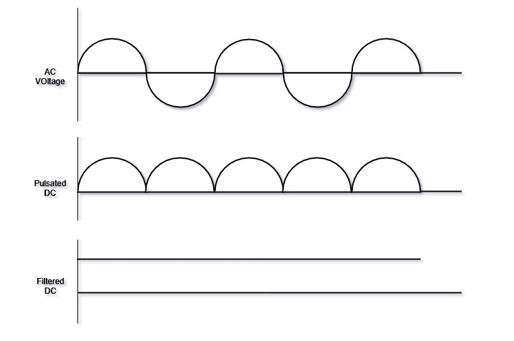
The full-wave rectifier circuit does rectify the AC voltage into DC voltage.
But, the pulse character is still intact in the converted/rectified dc voltage in the form of the ripple of a half pulse as shown in the waveform below.
In order to get the average value of the positive pulses in the obtained DC voltage, we must use a filter circuit or a capacitor which reduces the repel and approx our dc voltage waveform to the straight line.
Note: Cutting down on the pulse completely from the Pulsated DC voltage is very much impossible in practice.
The Full-wave Rectifier Circuit can be seen in a large number of applications from mobile-laptop chargers to power supply for various machinery.
Components of Full Wave Bridge Rectifier Circuit
- Four diodes
- Electrolytic capacitor
- Step down transformer.
Working of Full Wave Bridge Rectifier Circuit
This bridge rectifier circuit works on a simple mechanism.
- A step-down transformer is used in order to step down or decrease the high voltage AC into low voltage AC.
- The transformer’s secondary winding is connected to the opposite points of the bridge made up diodes. The secondary output of the transformer is connected at a point where both the anode as well as the cathode of the diode lies.
- All the four diodes are connected in such a way that they form a passage which allows only one side of the AC voltage or pulse and converts the negative part of it into positive voltage or pulse.
- The DC voltage output of the bridge rectifier circuit is obtained from the points where both the diodes are connected either from anode or cathode. The anode becomes the positive part as well as cathode becomes the negative part of the DC voltage output
- The output voltage of the bridge rectifier is not a constant/straight DC voltage but does have a pulse which is then reduced with the help of an electrolytic capacitor which acts as a filter to Pulsated DC voltage.
- The efficiency of the bridge rectifier lies in how the minimum amount of pulse it has after the filter is applied to the pulsated output.
- The full-wave Bridge Rectifier Circuit is complete as the capacitor or a filter is applied to decrease the pulse and the voltage is then used for various purposes.
Full Wave Bridge Rectifier Circuit Theory Explained
The working of the full-wave Bridge Rectifier Circuit is divided into two cycles which are then filtered in order to reduce the pulse or the repel on the DC voltage.
The two cycles of the Full-wave bridge rectifier are classified below:
- First half cycle
- Second half cycle
First half cycle
- The output voltage of the secondary winding of the transformer is in the first half of the wave that is the positive side of the AC voltage.
- In this condition, two of the opposite diodes connected will be in forward-bias and the current flows. The other two opposite diodes connected in the circuit will be in reverse-bias, so the current would not flow through those.
- During this cycle, the first half of the AC voltage is obtained as a half positive pulse of our desired DC voltage.
- Until the first half cycle, the path of the current remains from the anode of the first forward-biased diode to the cathode of the another.
- As the output voltage of the transformer drops to the zero voltage the first half cycle of the bridge rectifier circuit is completed.
Second half cycle
- Second half-cycle works as the opposite of the first half cycle.
- In the second half cycle of the output AC voltage from the secondary winding of the transformer, the opposite diodes are in forwarding bias (other than the diodes which are in forwarding bias in the first half cycle).
- In the second half cycle, the negative part of the AC voltage flows through the forward biased diodes leaving the rest of the two in reverse bias which was forward biased in the first half cycle.
- During the second half cycle, the path of the flow of current becomes from the anode of the first forward-biased diode to the cathode of the another, which ultimately follows the same direction of current as it was in the first half cycle.
- During this cycle, the second half that is a negative part of the AC voltage is obtained as another half positive pulse of our desired DC voltage.
The two cycles that are the first and the second half cycle combine and become a DC voltage.
However,
The generated DC voltage has a Pulse or ripple property which makes it less useful when it comes to using it as a proper power supply in various applications.
The remains of the pulse or ripple in the DC output of the full-wave bridge rectifier bridge is then rectified with the help of a capacitor.
After using the capacitor the ripple is reduced, the reduction of ripple depends on the rating of the capacitor (in µF mostly) used to filter the DC voltage.
Peak voltage is obtained and the output voltage is generated.
Applications of the Full Wave Bridge Rectifier Circuit
- Full Wave Bridge Rectifier is used to detect the amplitude of the modulating radio signal.
- Bridge rectifier circuits are also used to supply steady and polarized Dc voltage in electric welding.
- The Bridge Rectifier circuits are widely used in power supply for various appliances, as they are capable of converting the High AC voltage into Low DC voltage.
- Full-wave rectifiers are also used for powering up the devices which work on DC voltage like motor and led.
This full-wave bridge rectifier circuit is used more than the other rectifier circuits due to its huge number of advantages over others.
Also, watch Wheatstone Bridge Principle and Application

12 thoughts on “Full Wave Bridge Rectifier Circuit Working and Application”
very informative article ! Thank you for sharing this!
Thanks Alokita !
What would be the difference between the bridge rectifier and the full wave rectifier ?
Bridge rectifier uses the diode bridge in order to convert the AC voltage into a DC voltage where as another full wave rectifier (which you may indicate) consist of a transformer with a centered tap output. The DC voltage is outained by combining the positive voltages from the each side of the center tap.
Hope that helps you.
bridge rectifier is type of full wave rectifier
I thought that SMPS and rectifiers are the same ! But the SMPS does provides the more smooth DC voltage then the full wave rectifier. I was thinking that what is the use of the rectifier if we have some thing better !
Pardon me to disappoint you Nowrin. SMPS or the Switched Mode Power Supply has the rectifier in it. you may want to take a look at the working of SMPS. You will se that is provides the main unregulated DC voltage which is then converted into a regulated DC voltage.
Hope that make things more clear to you. 🙂
I used to be able to find good info from your blog articles.
Thank you Bro…..
Share more…
What is the use of full wave and half wave rectification in medical field I.e in therapeutics?
Dear Ayesha,
Rectifiers are used for giving DC supply after converting it from AC. Also, most of the medical instruments mainly work at low voltages high frequency. Thus you can understand it as if any of the medical instruments need a particular low voltage, then we can achieve it with the help of a rectifier along with a Zener diode. By the way, research is going on for rectifiers with higher frequencies.
I hope this info will help you. All the best.
Thank & Regards
What is the part number used for transformer in this circuit