Arduino Motor Control
If you are into electronics, then you must have heard about the arduino board. Arduino boards are in many types but the most popular one is known as Arduino Uno. There are number of simple application of the board you will find such as LED Blinker, Arduino motor control and many more which can easily be made through the Uno board.
In Motor control application by arduino, you will find number DC motors everywhere like toys, fans, tools etc. And, the torque of these DC motors is based on their physical specifications. The Arduino motor control uses DC motors which changes the direction as we change the direction of dc current which can be done easily with an arduino board.
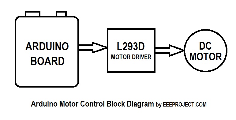
Components needed of Arduino Motor Control Circuit :
- A small DC motor (Shunt DC Motor)
- An Arduino board
- L293D Motor Driver (H Bridge)
- Switches
- Variable resistor (Preset)
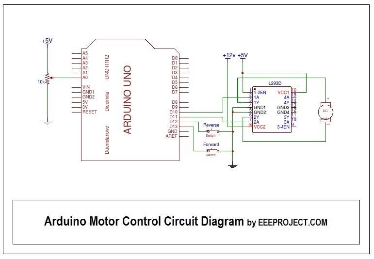
This Uno board is uploaded an arduino code according to which it establishes the arduino dc motor direction control. The below code can be used in order to control the direction of DC motor You can get a number of Arduino codes online. All you have to do is upload it in your arduino board using Arduio software.
Program for Arduino Motor Control
const int potPin = A0;
const int fwdbuttonPin = 13;
const int bckbuttonPin = 12;
const int pin1 = 11;
const int pin2 = 10;

int potValue = 0;
int motorValue = 0;
int fwdbuttonState = 0;
int bckbuttonState = 0;

void setup()
{

 pinMode(fwdbuttonPin, INPUT_PULLUP);
 pinMode(bckbuttonPin, INPUT_PULLUP);
 pinMode (pin1, OUTPUT);
 pinMode (pin2, OUTPUT);

}

void loop()
{

 potValue = analogRead(potPin);
 motorValue = map(potValue, 0, 1023, 0, 255);
 fwdbuttonState = digitalRead(fwdbuttonPin);
 bckbuttonState = digitalRead(bckbuttonPin);

 if (fwdbuttonState == LOW)
 {

 analogWrite(pin1, motorValue);
 digitalWrite (pin2, LOW);

 }

 else if (bckbuttonState == LOW)
 {

 analogWrite(pin2, motorValue);
 digitalWrite (pin1, LOW);

 }

 else
 {

 digitalWrite (pin1, LOW);
 digitalWrite (pin2, LOW);

}

}
Working of Arduino Motor Control
Arduino motor control is used in DC motors for efficiently controlling the speed and direction of the motor without the help of integrated motor driver.
- For adjusting the speed of the motor, the one pin of the motor is attached to the analog pin of the arduino. And, when the connections are made the motor moves in the normal forward direction in our desired speed.
- Then, when the button connected to another of arduino is pressed then the direction in which the motor was moving is reversed. And, until the button is not released it keeps on moving in the same direction.
- Transistors are there to efficiently control the forward direction of DC motor.
- And, when the button is presses another set of transistors work to provide reverse direction to the motor, until the button is released.
Servo Motor Control By Arduino
With an arduino You can also control Servo motor which work on direct current but need an additional data input which decides which angle the servo should hold.. They basically have a separate field winding and the armature winding of the direct current (DC) source. These types of motors are used more often than others because they provide a fast and controlled command to the motor. The signal or command generated from these motors are very accurate that is why the response of the motor is quick and rapid. They also respond to the stop and start command in fraction of seconds because of the separate winding of the DC source. You will mainly found these types of servo motors in the numerically controlled equipment and simple appliances.
Short description of Arduino Uno board
The arduino motor control is established using an arduino Uno board. Uno board is the most commonly used type of arduino board. The reason it is most preferred board in electronics is that it has all the essential elements in it. Like,
- 7805 Voltage Regulator
- Power USB
- Crystal oscillator
- Power
- Pins
- Arduino reset
- Main microcontroller
- Analog pins
- Power LED indicator
- Analog Reference (AREF)
DC motors
The DC motors are used for direction purpose which are operated at the signal obtained by arduino. The purpose of choosing DC motor in Arduino Motor Control is that it changes the rotational direction as we change the direction of DC Current.
Applications of this arduino motor control are as follows :
- Arduino Motor Control is used in cleaning robots.
- You can spot the Arduino Motor Control very easily in robots and school projects.
Also watch solar battery charger circuit

5 thoughts on “Arduino Motor Control [Explained] in Detail”
Hi, i have made a robot with the metallic geared motors with the battery powering upto 12V and 10A. The motors i use are very compatible with the source also they are fast as hell and generate the torque that can not hold them to stop.
I have the problem that till now i have burned almost 7 L293d ICs, i guess they are not made for the job like the one i’m doing with them.
Can you suggest some better alternative of L293D for such task as i have to perform ?
I would highly recommend you to use the power transistor after the motor output pin so that you can supply sufficient power to the motor. Well you do not like to do circuit things then you can go for L298, which works the similar as L293D but ar a larger current.
I’m still not sure that it can perform that weather it will perform on the current such as 10A. However, i would suggest you to use the good heat sink attached with the IC in order to protect it from overheating.
Do share your experience with L298 Driver IC, we would appreciate it. 🙂
Can I control more than a two motors at a time with the driver which you have had explained ?
sure you can control more than two motors, all you have to do is to use the more L293D drivers. Since, each driver has a room for two motor to control at the the different signal (which we define through arduino or a microcontroller).
We need to use the respective number of L293D drivers as the number of motors we need to control.
Hope that helped 🙂
Hey, I saw a video of someone who made the arduino board by himself ! 🙂