Parity Bit
Before studying the main topic, let’s discuss what do we mean by a parity bit. Well, it might be a 0 or 1 in data transmission, depending on the type of Parity checker or generator (even or odd).
Thus the bit that is added to the word containing the binary information for making the number of 1’s odd or even is said to be called as a Parity bit.
Also, watch Motion detector circuit
Parity Generator and checker
The parity generator is a digital logic circuit that generates a parity bit in the transmitter. But when we talk about the Parity Checker, it’s a combinational circuit that checks the parity in the receiver.
The sum of the parity bit and data bit might be even or odd. In even parity, the total number of 1’s by adding both parity and data will be even. Whereas, when the odd parity is used the sum total of data and parity bit makes the total number of 1’s an odd value.
The fundamental principle in parity circuits is that the sum of even number of 1’s is always 1 and that of the odd number of 1’s is always 0. Such a circuit can easily be implemented by using the Ex-OR gate ( as it gives 0 when the number of inputs is even).
What is the parity generator?
It is a combinational circuit that takes n-bit of information (data) and generates an additional bit to be transmitted along with the n-bit data.
In the Even Parity scheme, if the number of 1’s is even in the data stream (info), then the parity bit is ‘0’ whereas when the total number of 1 count to be odd then ‘1’ is the parity bit.
In the Odd Parity scheme, if the number of 1’s is even in the data stream then ‘1’ is the parity bit but when the number of 1’s is odd then ‘0’ is used as the parity bit.
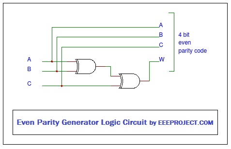
For an Even Parity scheme, the combinational circuit is shown below where 3-bit of data is accompanied with a parity bit (maybe 0/1 depending on the data stream).
Now let us understand both Even and Odd Parity Generator in a better way with the help of an example each.
Also, watch FM transmitter
Even Parity Generator
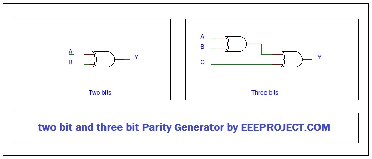
Let us consider a 2-bit message to be transmitted with an even parity bit. Let the 2 inputs A & B are applied to the circuit and Y is the output bit parity. Now to generate the even parity bit Y, the total number of 1’s must be odd.
The below-shown is the truth table of Even Parity generator where the output (parity bit generator) becomes 1 when the number of inputs is odd else output remains 0.
| 2-Bit Message | Even Parity Bit Generator | |
| A | B | Y |
| 0 | 0 | 0 |
| 0 | 1 | 1 |
| 1 | 0 | 1 |
| 1 | 1 | 0 |
The K-map simplification for the 2-bit message even parity generator is
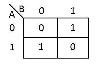
From the above table, the simplified expression of parity bit can be given as:
Y= A’ B + A B’
Y= A ⊕ B
The above expression could be implemented using an Ex-OR gate. The logic diagram is as shown. The 2-bit message along with the parity bit is transmitted to the receiving end where the checker circuit checks for the error.
Odd Parity Generator
Let us suppose 2-bit data is to be transmitted with an odd parity bit then the 2 inputs being A, B & Y will be the output (odd parity bit). The total number of 1’s must be even in order to get the odd parity bit.
In the below truth table, the parity bit ‘1’ is generated when the total number of 1’s is even in data bit (to make it odd).
| 2-bit message | Odd Parity bit Generator | |
| A | B | Y |
| 0 | 0 | 1 |
| 0 | 1 | 0 |
| 1 | 0 | 0 |
| 1 | 1 | 1 |
Using K-map, the above truth table can be simplified as below:
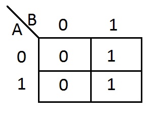
The expression for output parity bit Y can be given as:
Y = A’⊕ B (Ex-NOR )
This expression can be implemented by using one Ex-NOR gate. The 2-bit data along with the parity bit is transmitted to the receiver where parity checker checks for the error in the message.
Parity Checker
This circuit is used at the receiver where it checks for the possible errors in the message data. Also as Parity Generator, Parity Checker is of two types namely, Even Parity Checker and Odd Parity Checker.
Even Parity Checker
Let us suppose, the 2-bit input message along with the parity bit comes from the transmitter end. Thus 3-bits are applied as the input to the parity checker where it will check for the possible errors.
If the number of 1’s received at the receiver end is even then, the message received is error-free. But if the number of 1’s counts to be odd then the received message contains an error.
The truth table for Even Parity checker can be made as follows, Parity error checker Ee is 1 when the number of 1’s counts to be even, else it will be 0.
| 3-bit Message Received | Parity Error Check | ||
| A | B | Y | Ee |
| 0 | 0 | 0 | 0 |
| 0 | 0 | 1 | 1 |
| 0 | 1 | 0 | 1 |
| 0 | 1 | 1 | 0 |
| 1 | 0 | 0 | 1 |
| 1 | 0 | 1 | 0 |
| 1 | 1 | 0 | 0 |
| 1 | 1 | 1 | 1 |
Odd Parity Checker
Now, let us assume the same scenario as above where the 2-bit input data along with the parity bit is transmitted through the transmitter. So in total, 3-bits are applied at the input of the Parity Checker.
Since the parity checker used here is an odd one, so the error will be decided on whether the number of 1’s is odd or not. If the number of 1’s at the receiving end counts to be even in number then an error has occurred. But if the number 1’s is odd then the transmission is taken as error-free.
The truth table for odd Parity Checker can be drawn as follows:
| 3-bit Message Received | Parity Error Check | ||
| A | B | Y | Eo |
| 0 | 0 | 0 | 1 |
| 0 | 0 | 1 | 0 |
| 0 | 1 | 0 | 0 |
| 0 | 1 | 1 | 1 |
| 1 | 0 | 0 | 0 |
| 1 | 0 | 1 | 1 |
| 1 | 1 | 0 | 1 |
| 1 | 1 | 1 | 0 |
Parity Generator/Checker Advantages and Disadvantages
The advantage is its simplicity and ease of use. But along with these, there are few disadvantages also which are as follows:
- If there are errors in more than 1-bit then parity checker won’t be able to detect it.
- No way to find which bit is corrupted.
- Data correction is not possible, so data has to be retransmitted.
You may also like Touch Sensor explained

103 thoughts on “Parity Generator and Parity Checker”
thanks its awesome
awesome
good
nice and Informative
How to control the signal ?
thanks very helpful
nice work
Please provide real time application in parity generator and parity check
Please make a video on parity generator
Very helpfull
Very informative post
Good work !
Superb..!!!! All informations are covered
Please tell some important applications for parity generator and parity chck
Is exnor or exor or both In the odd parity generator. It is confusing with sentence and figure
it is covered all topic.it is very help full for me.
awesom nd tq
nice
Good information
how does a one control the system with the feedback ?
thanks very helpfull
Please explain with better image.
thank you
Nice piece of info. Thanks!
hi friends,
I am looking for a VHDL code of Parity checker/decoder please guide me through.
Thank you
I need to design 3 bit parity generator which has 3 input data A, B and C also 2 even/off parity outputs. Need some help.
i make parity generator with NAND gate
good
i want to make 6 bit parity generator, please help me,thankyou
Hi,
I Want to design a circuit that takes a serial data stream from data in input. I want to get the high output if the data in the previous clocks have en even number of 1.
helpful, thanks !
nice article
How can i make parity generators with the help of universal Gate
Please also provide the guide to prepare my own circuit for parity generator and parity check.
Need more further details about how to design a generator with a feedback. Rest is just fine
helpful
Helpful
Need a little guidance to increase the bit number of my current parity generating system.
Good, The parity generator definition is some what precise
i have a virtual parity check, i want to redesign it to add up some more bit, how can i do so ?
what is the difference between parity checker and parity generator ? the general difference i’m asking anyone ??
very helpful
can i design a 6 or 9 bit parity generator using ic 74180 ? If yes please tell me how ?
how the Parity checkers and generators helps in detecting errors in binary data streams ?
how can i calculate parity bit of the system ?
i’m still not clear with detecting errors with the parity generator :!
I was about to design a generator, i need your suggestion regarding power balance input and out.
i was working on parity generator verilog code, i found a problem while using nand gate at the output feedback terminal, it’s supposed to compliment/not the signal, but it seems not to be working.
please explain odd parity checker and its logic diagram, i’ll be a lot helpful
state diagram of the parity generator where is it ?
please provide the truth table of various bits
can you tell us that where can we find the application of parity generator and parity check in real world ? i’ll help better understanding the their application
please do provide or link to a source where i can find truth table for an 8 bit parity generator, thank you
which logic gate should i use if i need to make an odd parity generator
what are the general basic difference between parity checker and parity generator
does exor used in even parity generator and exnor used in odd parity generator or does it vice versa ? its a bit confusing.
also do explain about arduino serial parity.
please 3 bit odd parity generator state diagram and truth table, i will be very thankful
which microcontroller is best for parity generator ?
please i seek for the C# or hexadecimal codes for parity generator, any bit will work.
can i perform parity generator with arduino ?
Please a PDF on Parity generator ICs
PCB print for parity generator with The IC
how to connect the parity generator and the parity check
i want to make a mini project for 2 bit parity generator, please help me
i need the verilog code for this
how to take a feedback from parity check as an input to another parity check
i make a 3 bit even parity generator but truth table is wrong values. plese help
please suggest a project for parity generator and check
what are the general applications of parity generator applications in real world ?
i do not understand how to get a feedback from the generator, please explain
how to begin with 4 bit even parity circuit ??
Thanks
Amazing article
How can i encode with parity Check Matrix ?
Please suggest a way to determine LDPC generator matrix form parity check matrix.
In parity generator and check, what will happen if i set the the parity bit to the medium ?
Please suggest some nice topics for the project i can make with parity generator circuit.
Can i use IC of AND or OR logic gate to make parity circuits ?
If a parity bit is added to a 6 bit word, how many output lines do i need after multiplexing?
I’m in a bit of confusion, that the truth tables of even parity checker and even parity generator are the same or would there be any difference ?
What are the applications of parity generator made up of Xor Gate in real life ?
How would I find a Parity Check Equation
If i add a single parity bit to a four-bit word, how many output lines will it be needed after multiplexing?
How can a parity checker be made using universal gates? What is its operation?
is it true that XOR gate is the only gate used in parity generation and detection circuit.
is there the truth tables of even parity checker and even parity generator ?
What is the importance of Xor Gate in parity generator and parity checker ?
Can change the parity of time if i change the parity operator?
What will happen if i change the parity bits changes to medium in parity generator and the parity checker ?
Are there any disadvantages of parity generation code ?
Yes, it can detect only single bit error, if more bits are corrupted then this fails.
How can i assign a bit in Parity generator VHDL program
is the using XOR gate only the way to perform parity generator ?
is there the simple way to calculate the even parity bits for the the big number as such as 32 bit or 16 bit ?
please provide some nice project on digital circuits for parity generator and parity check
what does the ‘use’ statement does when i do program for the parity generator or parity check ?
i made 4 bit parity generator circuit. IS there any way i can add up more bits on it, or double it more precisely.
thanks for sharing the link, i really appreciate it.
Perhaps, you need to improve the info you’ve provided.
on the first sight i suspected that all here is a useless info but your other helpful piece of info such as Wheatstone bridge, Touch sensor, full wave rectifier, fm transmitter circuit etc made me think that you can enhance this content as well.
Keep doing nice work anyways !
Sure we are on it Travis. Soon you’ll see a better version of content.
Please how can i develop VHDL code for the 8 bit even parity check ? Very very urgent
Thanks for the appreciation. This motivates us to do better each day
Thanks Fricke. Yes you can explore out full site and can dig through many interesting posts.
Sir it is best but can u tell the how we circuit this Ic 74180 in logisim app.